
Review: #42082 Rough Terrain Crane
The 2018 flagship is the biggest Technic set ever, with a whopping 4057 pieces. Expectations are sky-high, as are the huge red extendable boom! Let’s see how this set really measures up!
Mobile cranes have been a common theme over the years, and have given designers an opportunity to really push the limits in terms of size, with the huge #8421 in 2005 and the even bigger #42009 in 2013. (Each of them was the largest Technic set to date, and each introduced significant technical innovations).
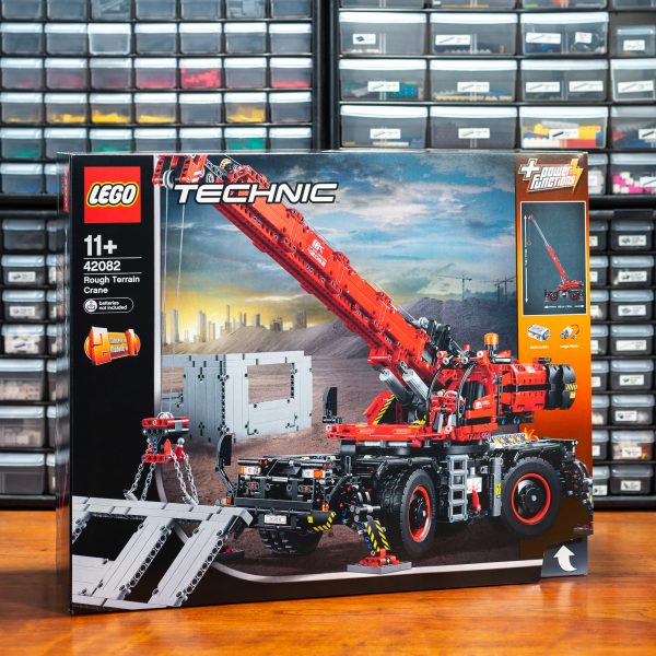
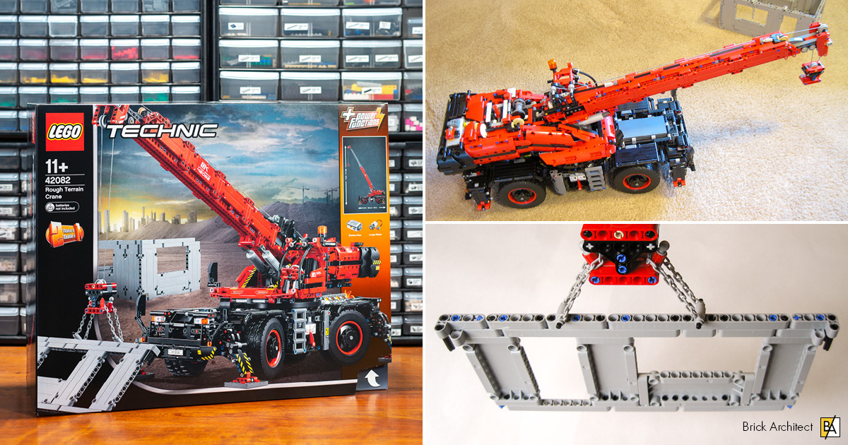
#42082 Rough Terrain Crane (Image: Tom Alphin)
Is it possible to go even bigger? Yes, apparently it is! According to the information provided on the huge box, the #42082’s boom can reach up to one meter (39”) high, and it has several motorized functions powered from a single L-motor. In particular, it boasts motorized 360-degree rotation of the superstructure, one thing that was missing from those earlier models. All this presents serious technical challenges, so it’ll be very interesting to see how they are handled. The red and black color scheme looks great. It makes a welcome change from yellow!
About the set
With a release date of 1 August 2018, this year’s Technic flagship has 4057 pieces and a RRP of $299.99 (€229.99 / £229.99).
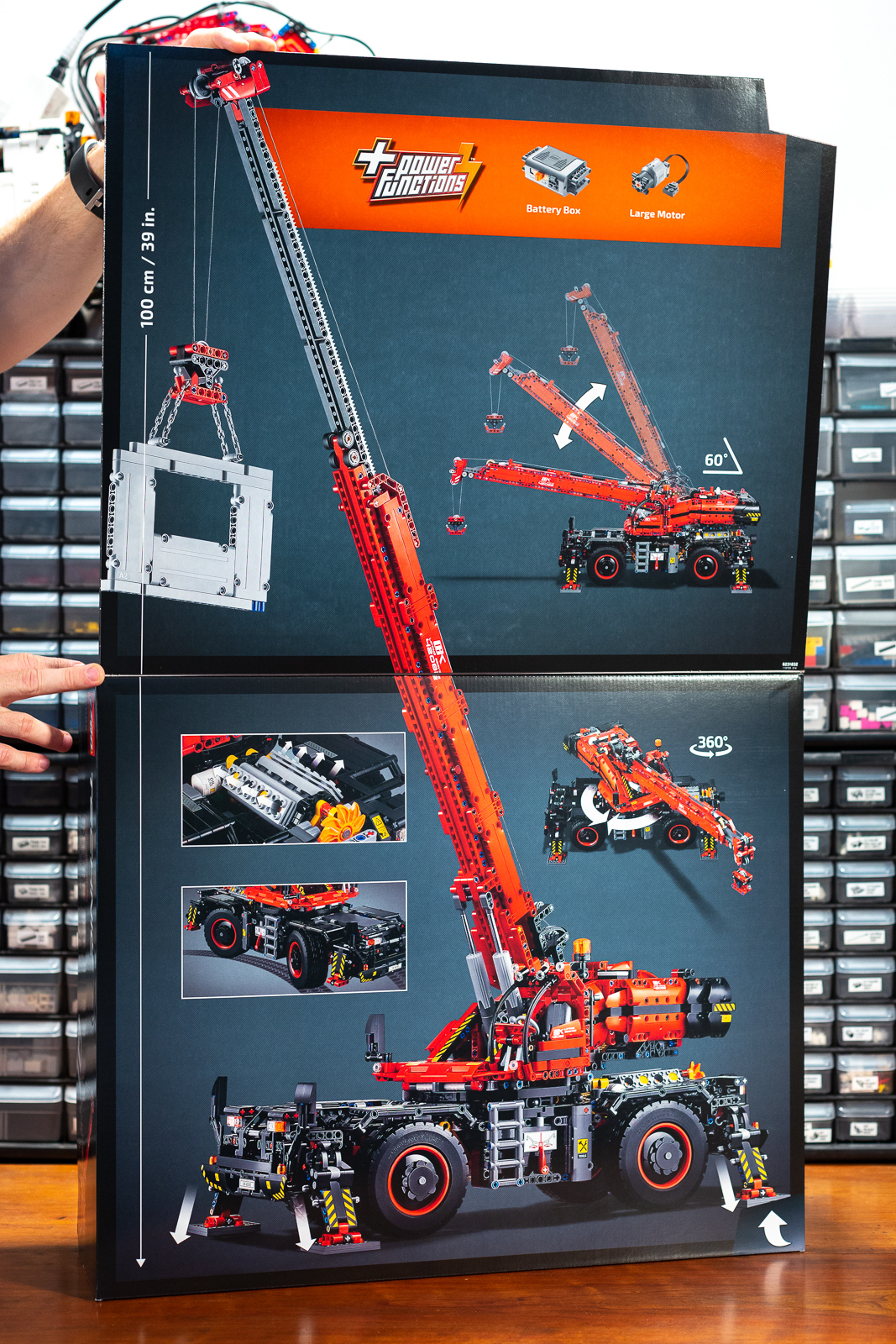
The box flap helps you understand that this is a big set!
Build process
The build is divided into 13 stages, each with its own numbered bags. The manual provides a helpful summary so we know what to expect. Time to get started on this monster!
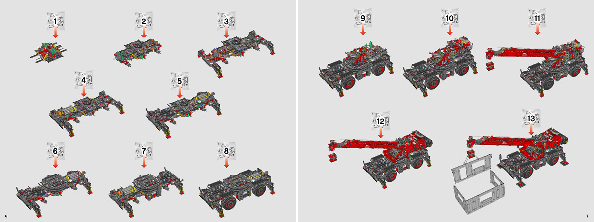
Instructions broken into 13 stages. (Image: The LEGO Group.)
Stage 1: Chassis gearbox
The first thing to be constructed is the gear selector mechanism in the center of the chassis. We kick off with some rather unusual part usage.
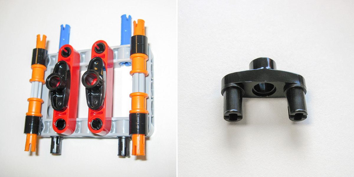
First steps (left), Part #15461 3L Two Pins, Pin Hole (right).
We will be seeing a lot of Part #15461 in this set (19 of them to be exact), with many different purposes. It makes me wonder if there was some kind of unofficial bet among the LEGO designers!
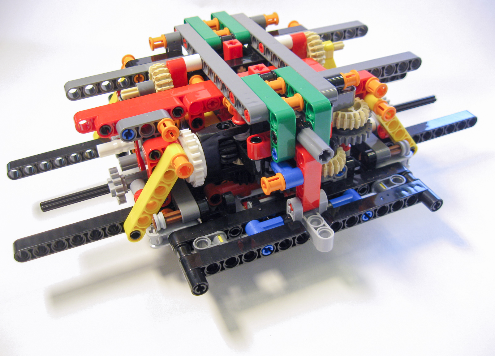
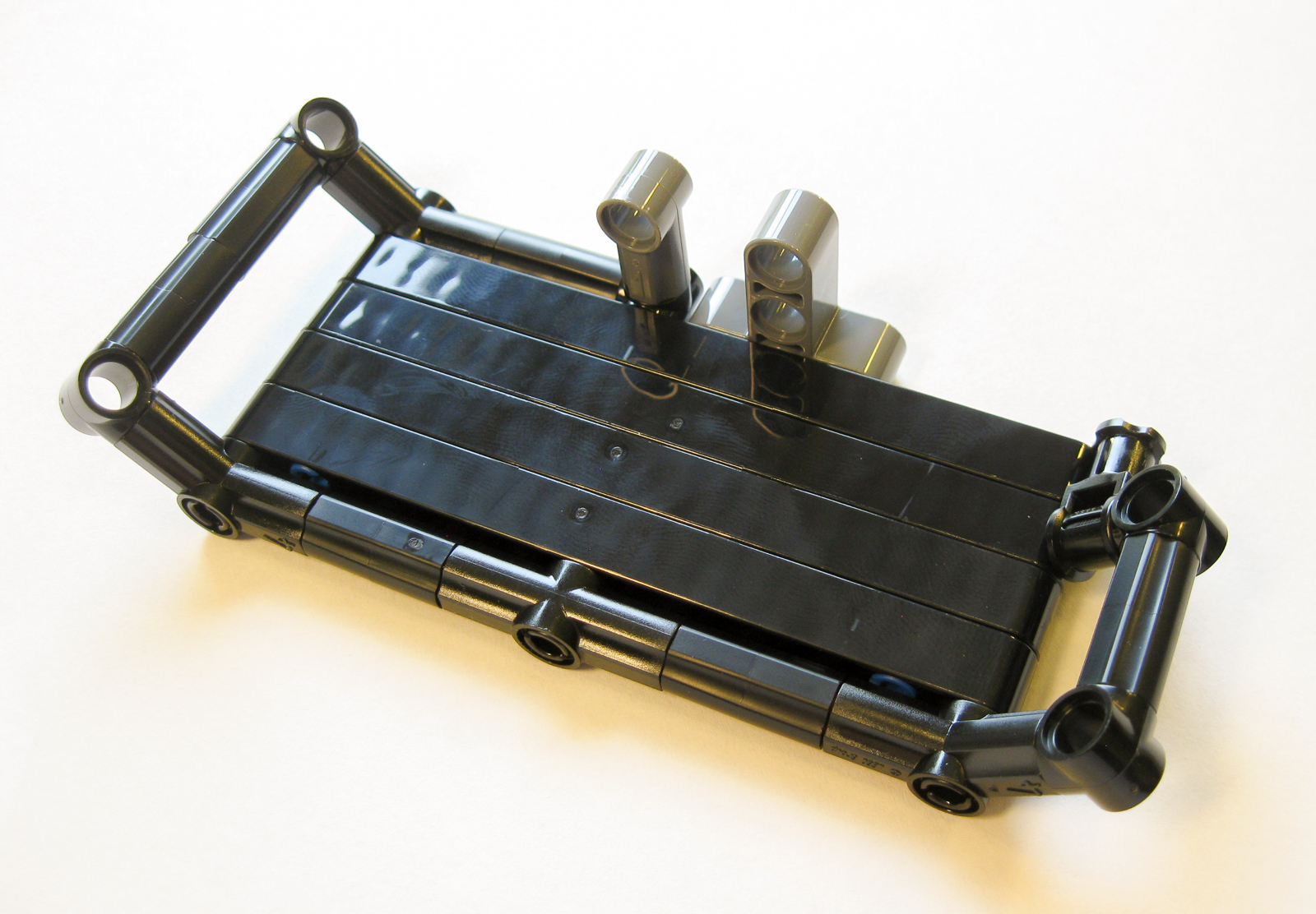
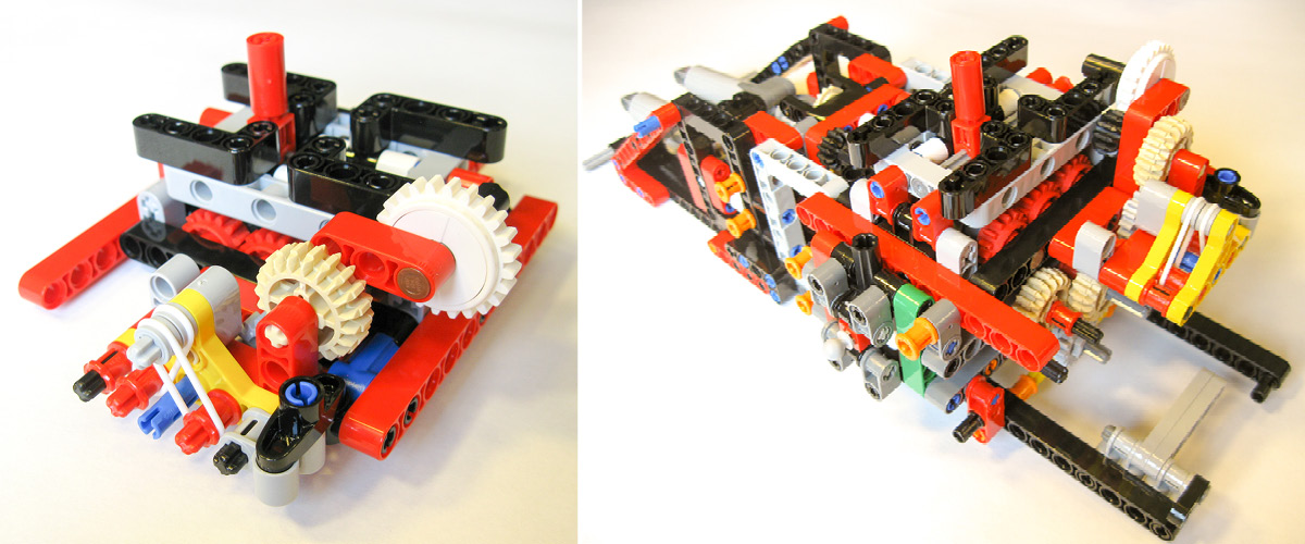
The completed gearbox.
Here is the result of stage 1. Although there are plenty of gears, it’s not quite as complicated as it looks. This assembly takes power from the superstructure (which will house the motor) through the center of the turntable to two gear selectors, which control two functions: outriggers, and rotation of the superstructure. The purpose of all those horizontal gears is just to get power from the gear selector back to the turntable where the superstructure will attach for the rotation (after appropriate gearing down). It would have been much simpler to control the superstructure rotation from within the superstructure itself, rather than routing power down through the turntable and then back up to the same turntable. However, that would make the function harder to operate: we would need to move a lever on the superstructure while it rotates.
Technic builders know the importance of ensuring that each mechanism runs smoothly before moving on to the next. Despite some effort I was not able to get this gear train running quite as well as I would have liked. There is considerable friction, seemingly because the bracing for these vertical axles is done in a rather ad-hoc way, with a tangle of connectors pointing in all directions. However, this is just a minor annoyance – it does not seem to seriously impact the final performance of the model.
Stage 2: Axles
Next, the two axle sections are added. The crane has four-wheel drive (driving a fake engine), two differentials, and four-wheel steering.
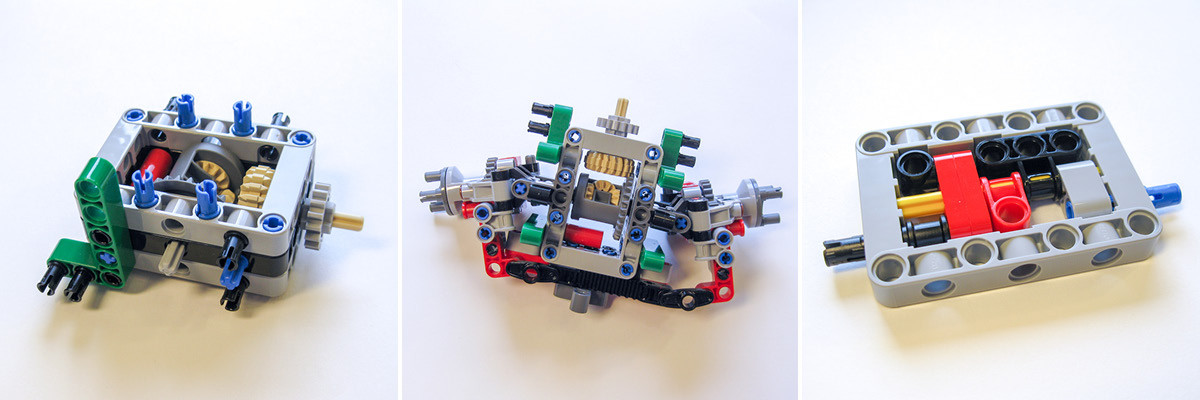
Over-engineering at its best! (left), Axle unit (middle), The ancient art of frame-stuffing (right).
Pivoting portal hubs will mean an alarming amount of tire-scrubbing when steering, but the differentials take care of it. And yes, that part is here again!
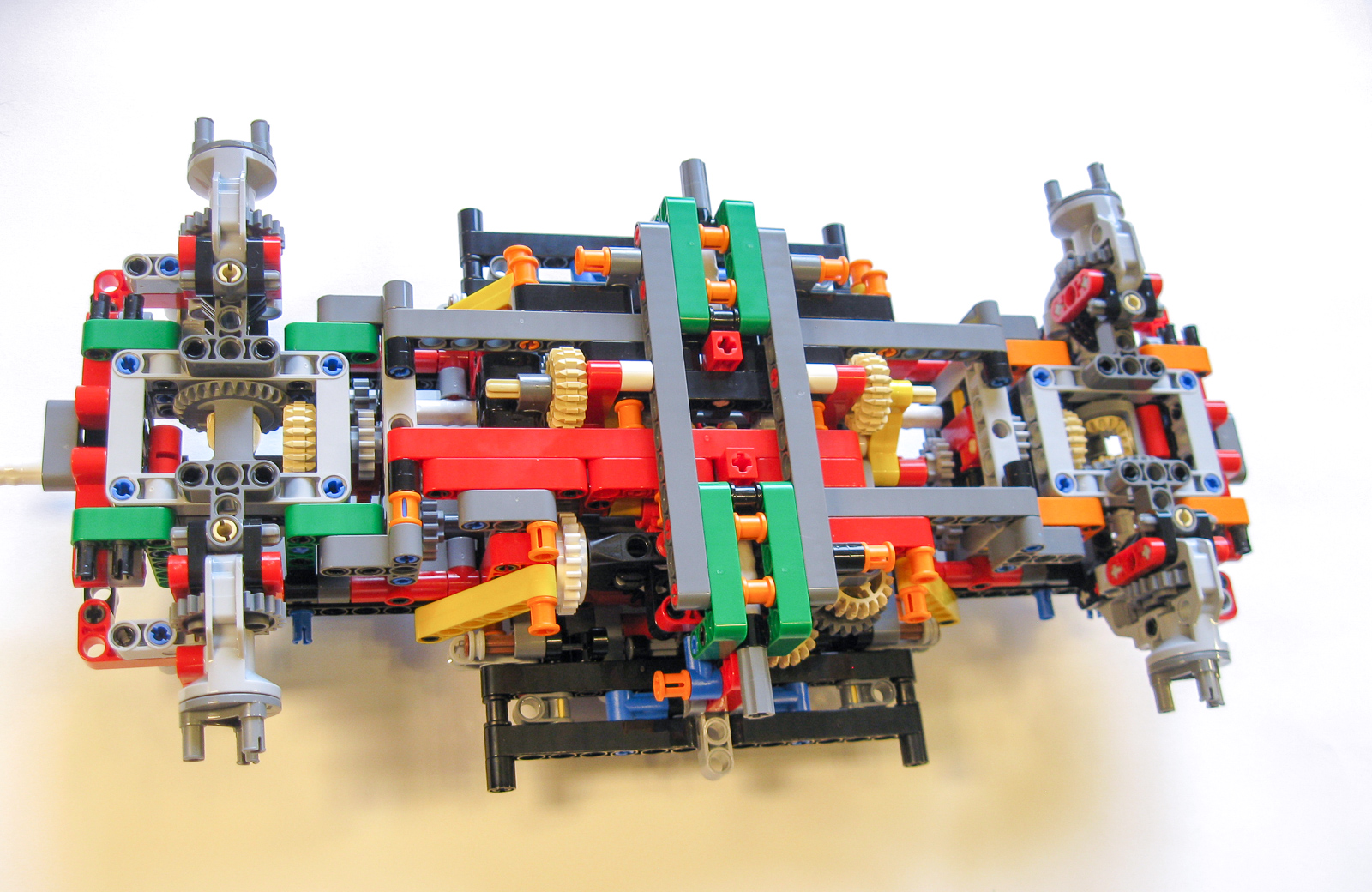
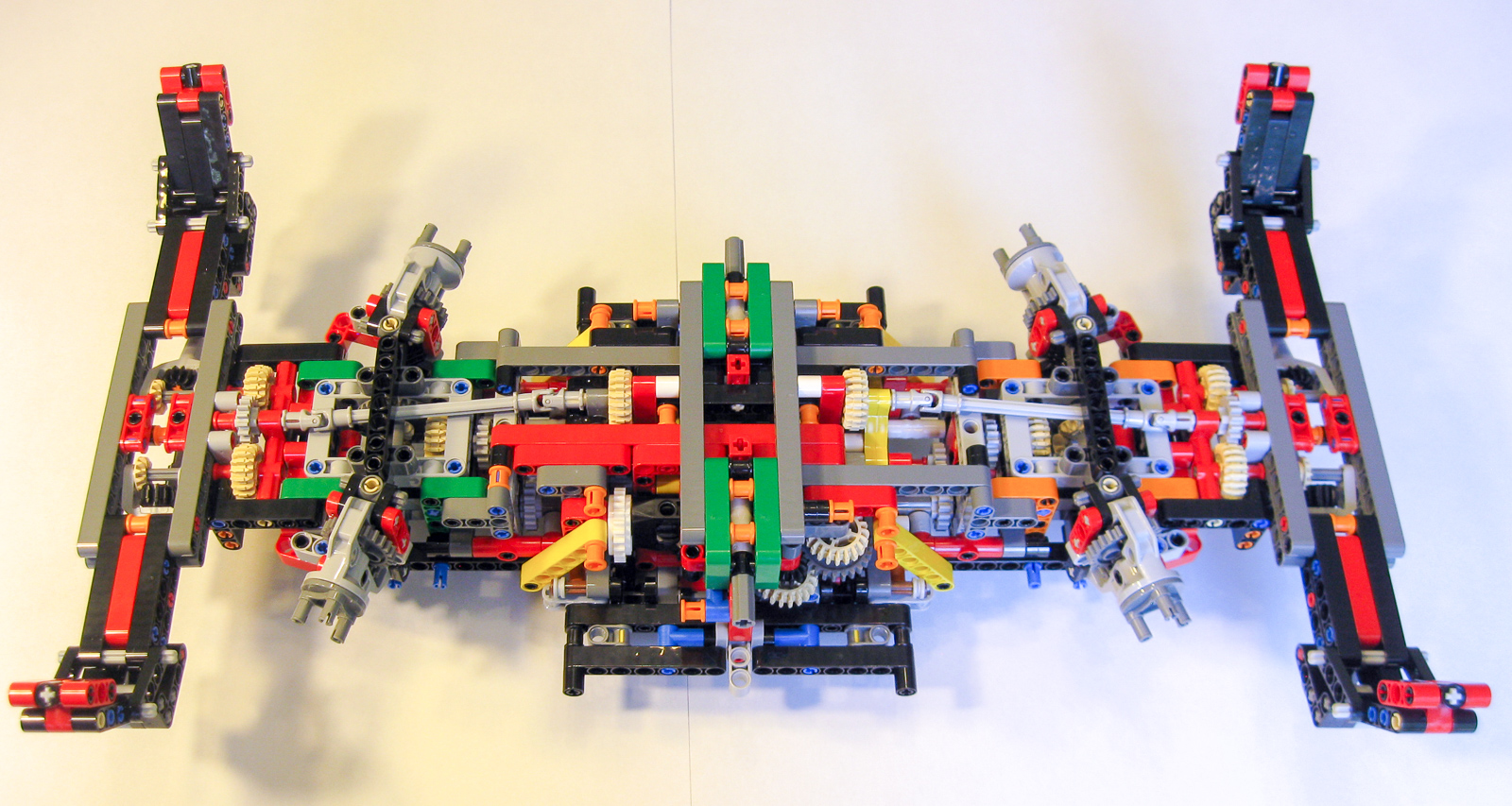
The colorful conclusion of Stage 2.
I was surprised how small the model looks at the end of Stage 2. There is a reason for the color coding. The chassis is almost (but not quite) symmetrical at this point. The green and orange parts enable the two ends to be distinguished easily, reducing the risk of assembling the later steps at the wrong end. It’s a nice idea, and I find it a bit surprising that the instructions do not highlight it more explicitly.
Don’t push it in yet!
I noticed a minor error in the instructions, one that might confuse an inexperienced builder. Back in Step 119 of Stage 1 we are instructed to partially insert four 3L stop-axles. But then throughout Stage 2 and beyond, these axles are incorrectly depicted as pushed all the way in. In fact, they are not to be pushed in until Step 545 of Stage 7.
Stage 3: Outriggers
Next, we need to add two outrigger assemblies.

Outrigger.
The outriggers employ mini linear actuators. Unfortunately, they lack the appropriate linkage to lock into place when in the down position, to take the stress off the actuator.
It’s getting a lot larger!
With the outriggers in place, the chassis is looking much bigger!
Stages 4 & 5: Steering and engine
In Stage 4, we add the steering knob and a V8 engine.
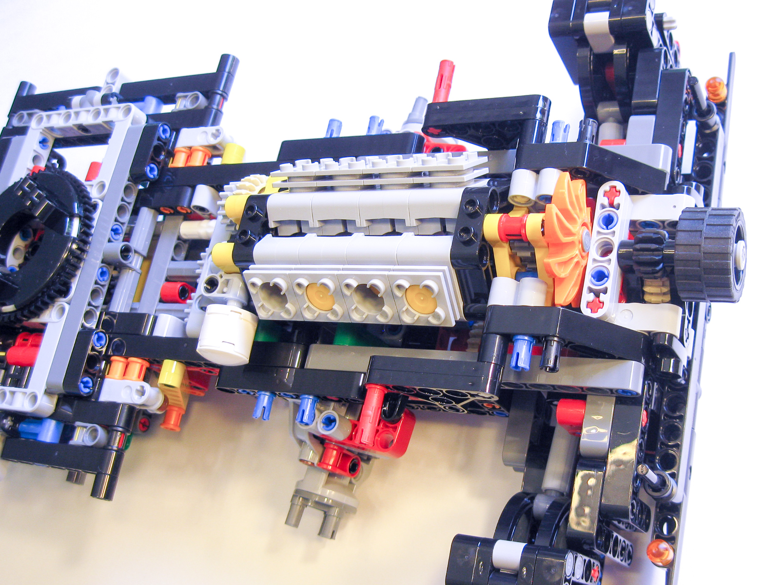
Engine and Steering.
In Stage 5, we add some strengthening to the other end of the chassis.
Stage 6: Turntable
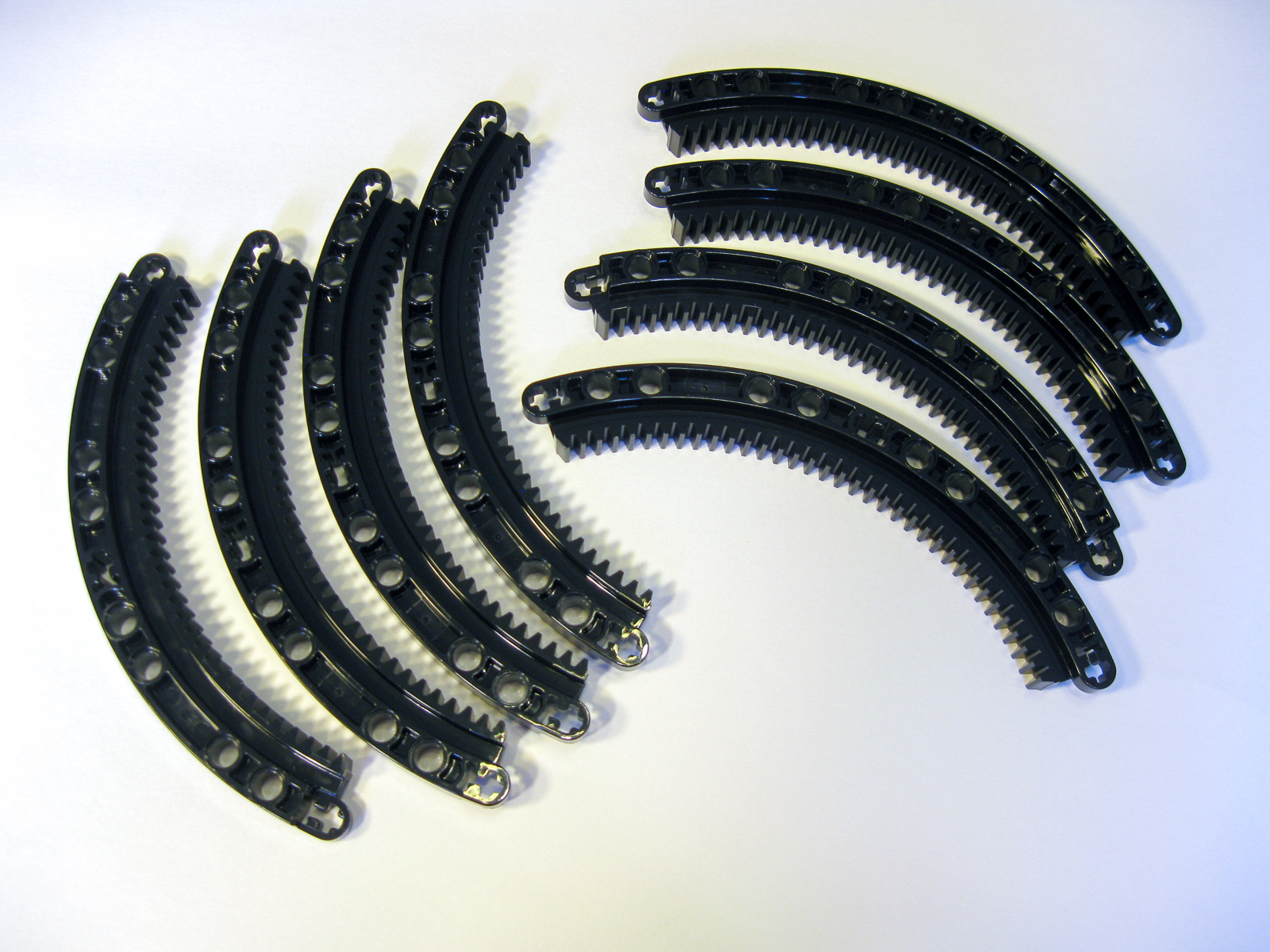
Here is where things get particularly interesting. A rotating superstructure like the one on this model needs a large and sturdy turntable that can support the weight without allowing it to rock sideways. The 60-tooth Technic turntable on its own is not adequate for the task – its diameter is too small and it has too much play. Four of the new large quarter-circle gears make a nice smooth ring, which seems like it should be helpful, but what is really needed is some kind of roller bearing to allow two such rings to rotate smoothly against each other. There is a tantalizing groove running around the edge of the ring, but what part fits into it? Several things have been tried in the LEGO fan community, but all of them have drawbacks. This model introduces the “official” solution, and it’s a beauty!
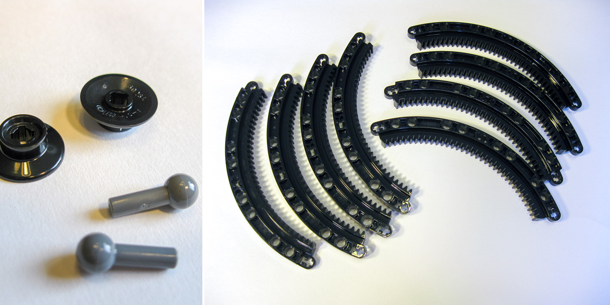
Part #50254 Train Wheel Small, Part #22484 Bar 1L with Towball, Part #24121 Gear Rack 11 x 11 Curved.
These mini train wheels (part 50254) are too small for a Technic axle, so need to be mounted on a minifig tool type part. Eight of them are mounted on a free-floating ring of Technic connectors which fits between the two rings of quarter-circle pieces.

This assembly makes for a perfect fit.
Was the quarter-circle piece designed with this assembly in mind? We may never know, but it’s a perfect fit, and the rotation is silky smooth. Bravo!
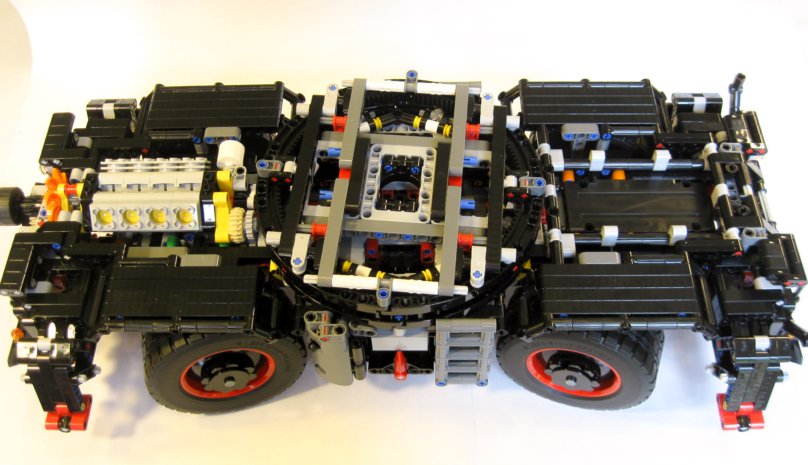
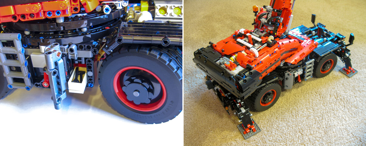
Stages 7 & 8: Side panels and wheels
Stage 7 adds control levers for the gear selectors at the sides of the chassis, and Stage 8 adds the wheels, together with various cosmetic features and strengthening. The wheel arches alone give a good idea of the size of this beast.
One of four wheel arches.
The wheels feature some unusual styling. To me the result looks rather cartoonish, but it’s a matter of taste.
Wheels and Wheel Arches in place.
Stage 9: Superstructure base and linear actuators
Now that we have a sturdy base, it’s finally time to move on to the superstructure! Stage 9 kicks off with the linear actuators that will be responsible for lifting the boom, together with a gear selector responsible for choosing between chassis and superstructure functions, and a bewildering array of gearing.
Starting the superstructure.
Here is another little oddity. The white 3L axle joiner shown at the center of the picture below has no axle going into it on the right side of the picture. A 2L axle here would seem to provide extra stability. Is this a mistake?
Why no axle for stability?
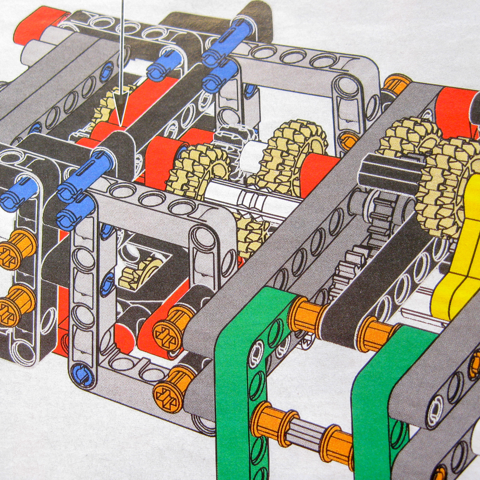
NOTE: You might notice that the linear actuators face in opposite directions and are mounted on a single load-bearing axle. As the boom is raised, the axles of the two linear actuators rotate slightly in opposite directions relative to each other, causing the actuators to extend by slightly different amounts. This puts more stress on one of the two linear actuators.
It would be better if the two 20-tooth gears faced in the same direction. I could not find an easy modification to achieve this, because the rest of the axle is taken up by connectors that play an important structural role. Fortunately, the effect is quite slight, and it does not seem to noticeably affect the operation of the final model.
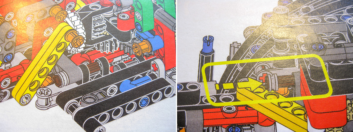
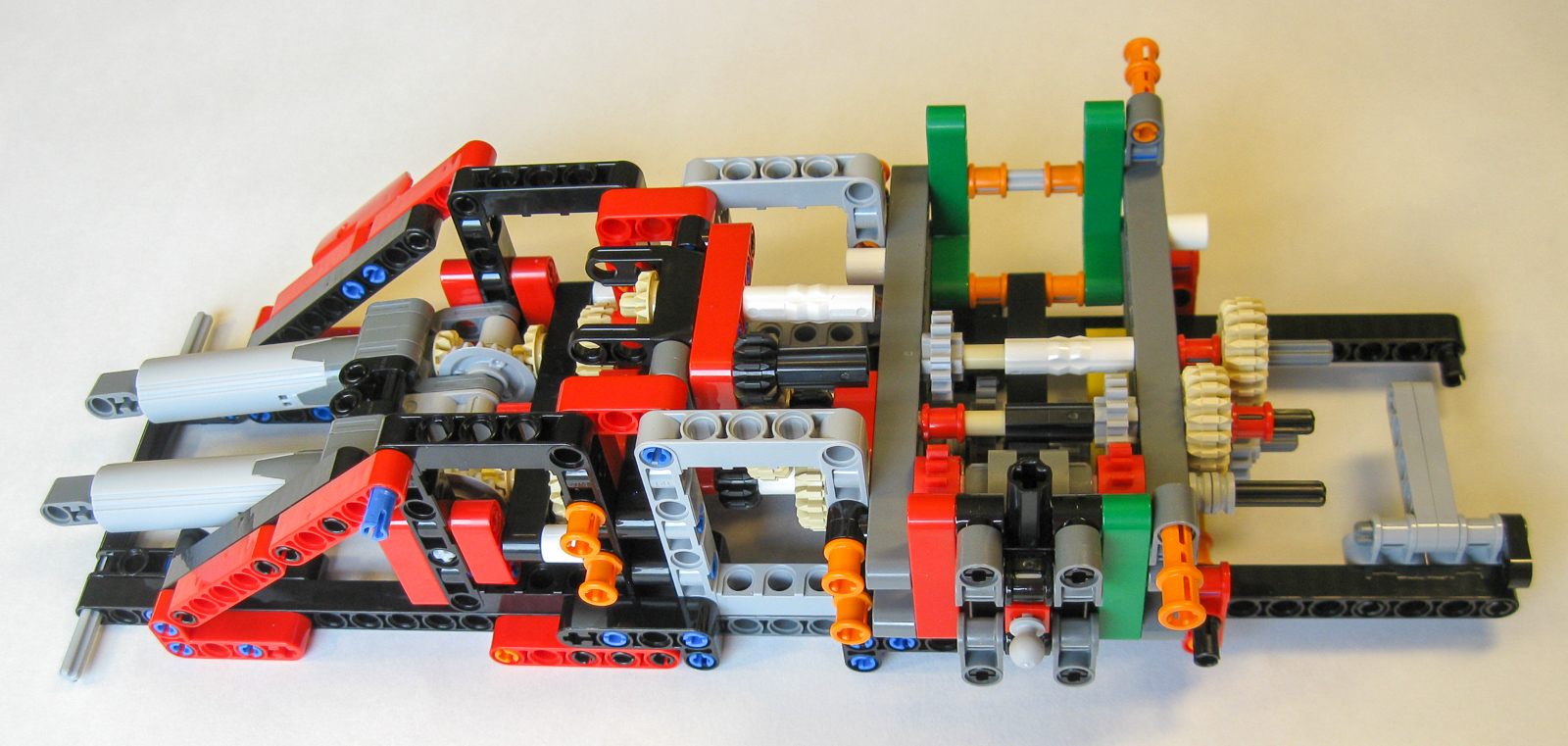
Stage 10: Superstructure gearbox and power functions
Stage 10 adds another gear selector, this one responsible for the three motorized superstructure functions. Much of the effort of Technic design goes into reducing friction, but here we have an unusual mechanism designed specifically to increase friction! The upper light gray axle with half-bushes is fixed and cannot rotate, so the two rubber bands provide resistance to rotation of the two red axles. These axles control two of the functions: boom extension and hook raising. Presumably the idea is to prevent unwanted movement of either function due to gravity or gearbox slippage. I do wonder how well the rubber bands will survive this treatment in the long term. Oh yes, and our little friend is back!
Last gearbox (left) attaches easily to previous gearbox (right).
This assembly plops straight on top of the previous gearbox. There’s plenty here to keep the gear-heads among us occupied and excited!
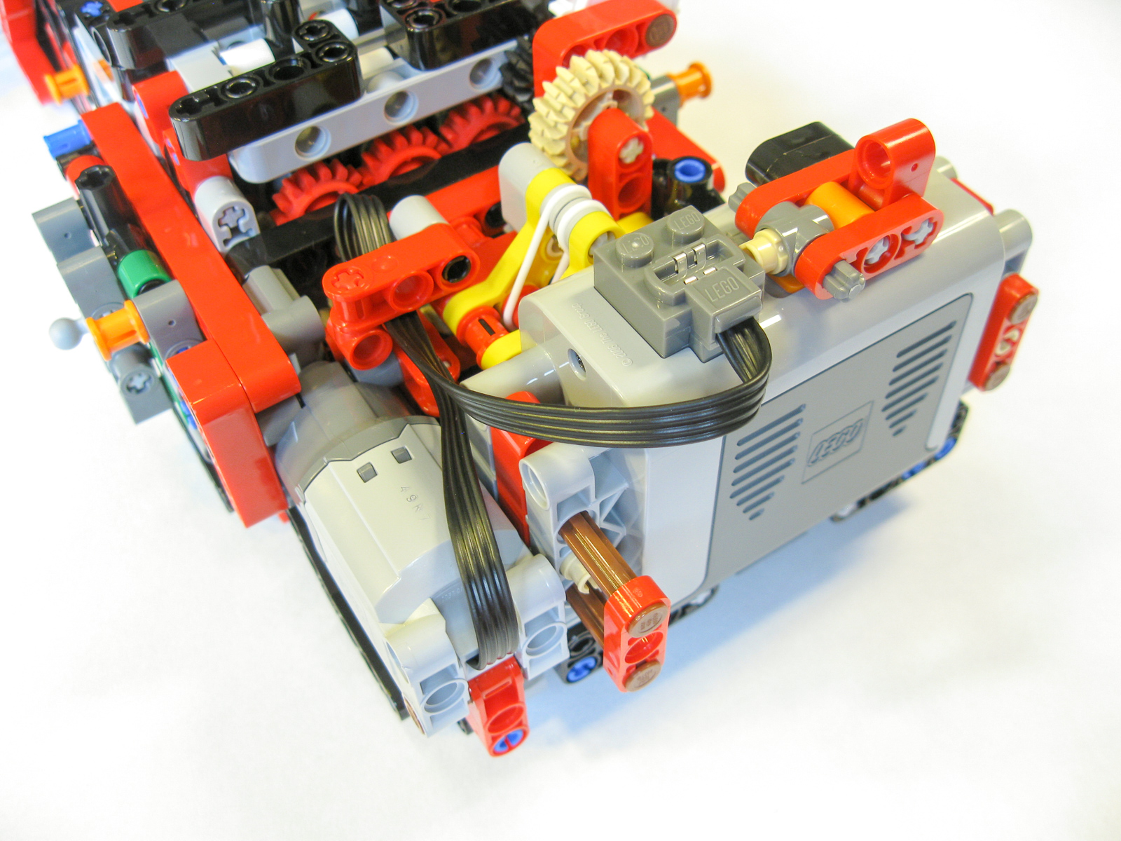
Battery box and Motor.
After that, we add the battery box and L-motor. Even here there’s lots of attention to detail. The battery box will form a counterbalance to the huge boom, and it has a one-way attachment on the switch, a little clip to hold the cable, and a quick-release system to allow easy changing of the batteries.
Ready to attach superstructure to Chassis.
Finally, we get to attach the superstructure to the chassis. It attaches easily to the center of the turntable.
Stage 11: Boom
Now we move on to what’s arguably the centerpiece of the model, a two-section extendable boom. The completed boom extends very smoothly, and it is remarkably strong and rigid.

Boom. It’s long.
Stages 12 & 13: Paneling and accessories
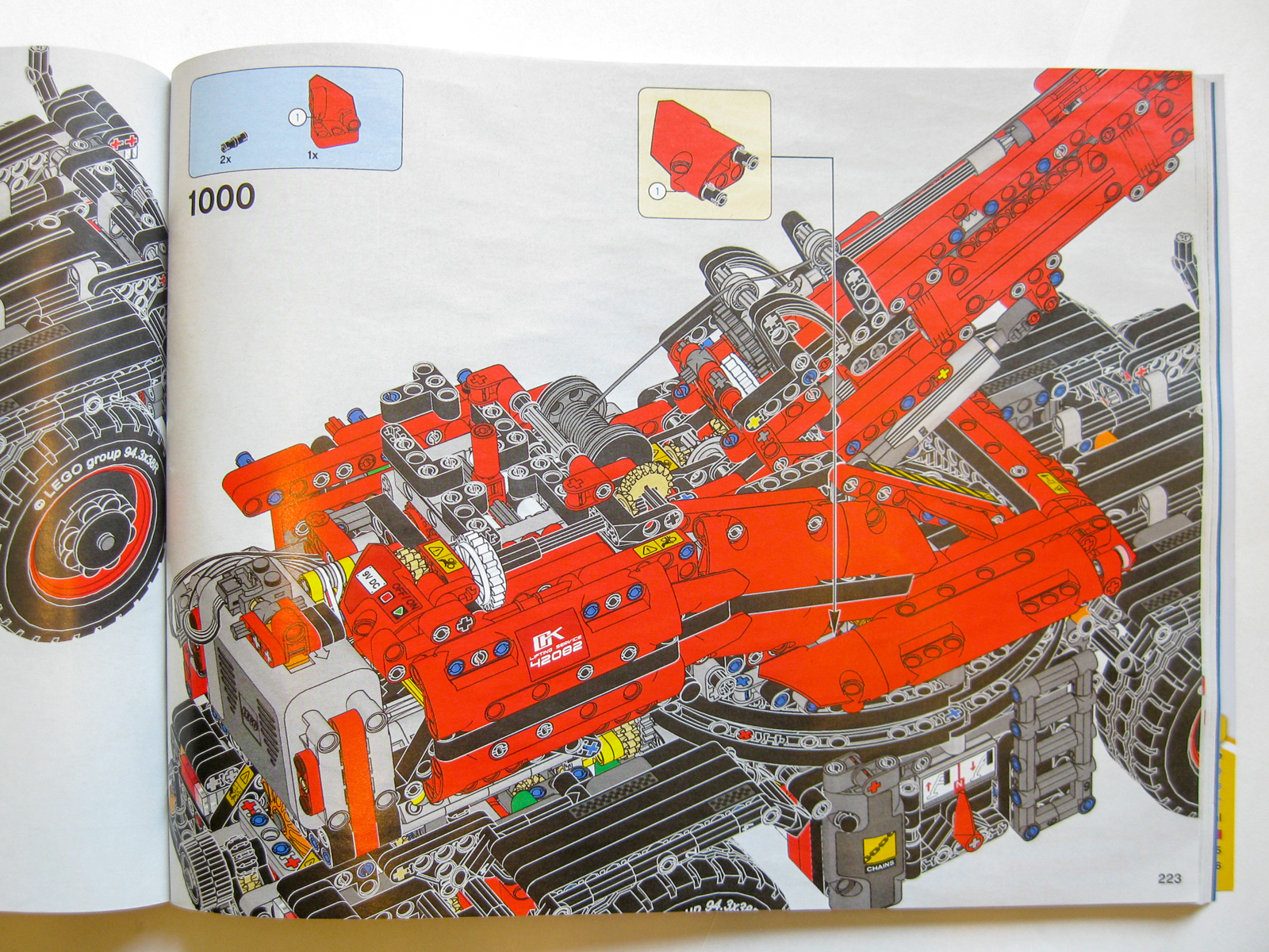
The crane is completed by the addition of various Technic panels in a distinctive red and black color scheme. There’s something surreal about instructions that run to over a thousand steps!
Time for some paneling.
This set continues the recent Technic trend of adding a few separate brick-built accessories of the kind that are more familiar in System sets. We get two little toolboxes, and four platforms to go under the outriggers, each with its own stowage area in the vehicle. There’s also a little fire extinguisher by the driver’s cab. These things don’t particularly excite me, but some will enjoy the added realism.
Toolbox (left), and outrigger platforms (right).
Last but not least, we need something for the crane to lift, and we get a whole house! Or rather, we get four wall sections which slot together to make the frame of a small building. There are two chains which attach manually to each wall section, allowing it to be hooked onto the crane.
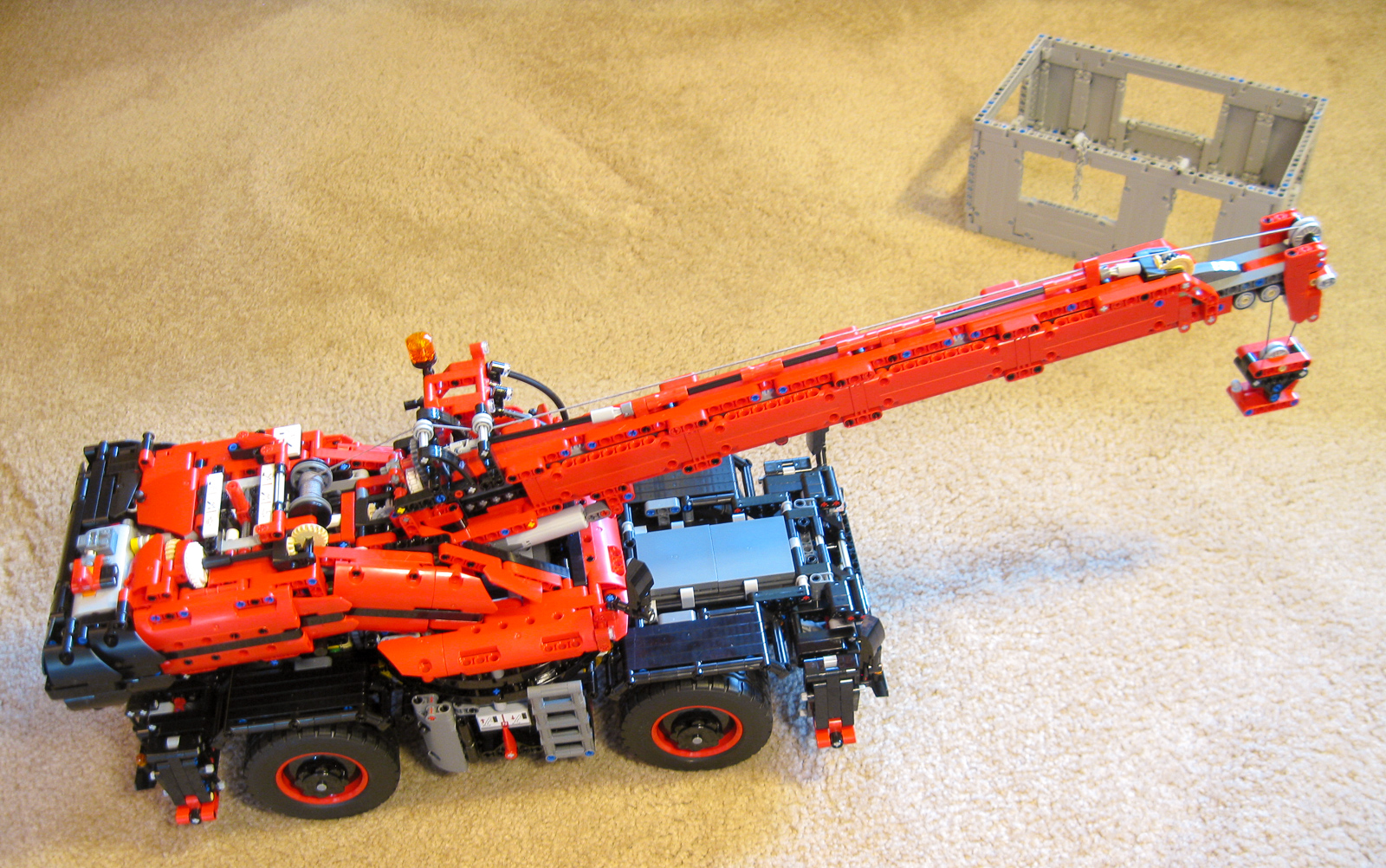
Completed crane with four-panel home.
Functions
There are two manual mechanical functions (steering and fake engine) and five motorized ones (outriggers, superstructure rotation, boom raise/lower, boom extend/retract, hook raise/lower). That’s an impressive list, but of course we should expect nothing less from the biggest flagship ever! All the motorized functions are powered by a single L-motor, via three separate gearboxes. Let’s have a look at the functions in more detail.
The gearboxes themselves are of the type first introduced in the Crawler Crane #42042: the motor only rotates in one direction, and the direction of motion of the function is selected by moving the appropriate lever in either direction. This makes for a very intuitive and convenient control experience. One selector (located on the superstructure) selects between the three crane functions on one hand, and outriggers and superstructure rotation on the other. (This ensures that the two cannot be run simultaneously – perhaps intended as protection against overloading the motor). Two separate selectors located on the chassis control the outriggers and the superstructure rotation respectively.
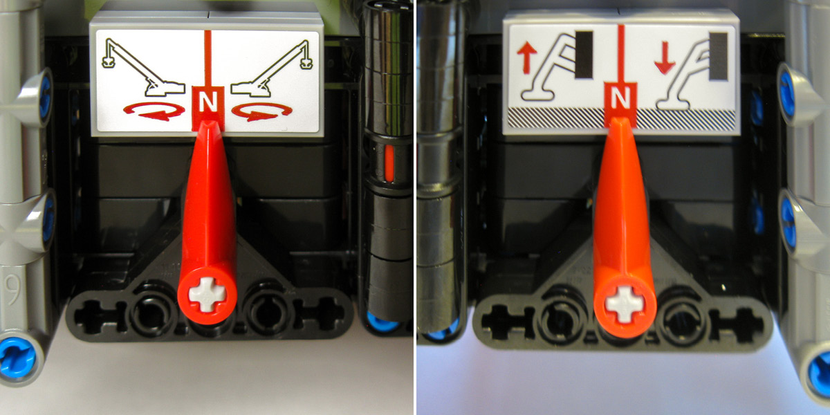
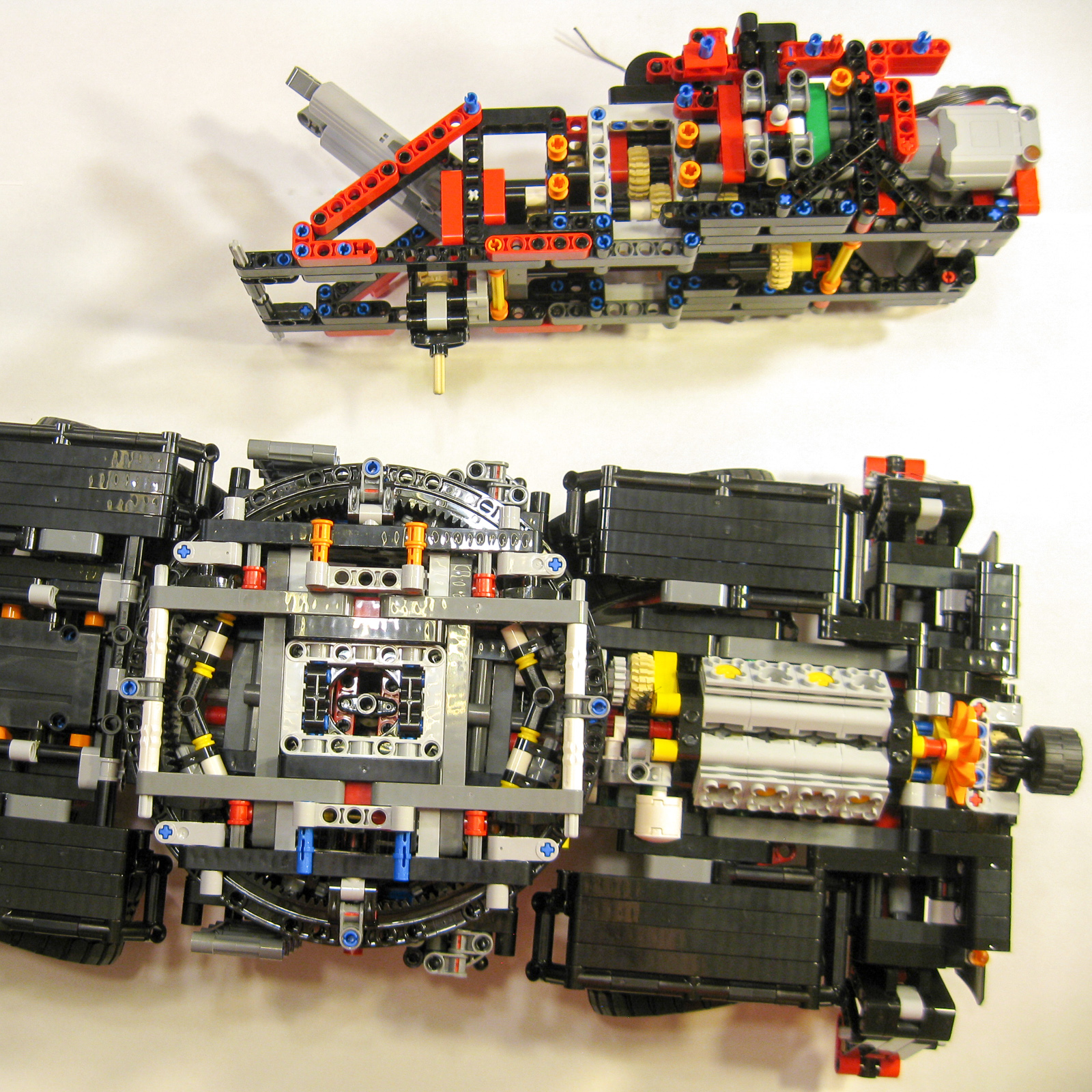
Chassis function selectors.
Finally, another selector located on the superstructure controls boom raising, boom extension, and hook raising. This one is a gate-style gear shifter, again ensuring that only one function can be run at a time. All the selector levers operate nicely without problems, and there are stickers to indicate which lever does what.
The crane rolls easily, and spins the V8 engine at a nice satisfying speed. It’s good to see genuine four-wheel drive (with two differentials). The four-wheel steering achieves a respectably tight turning radius. The rotation center of the wheels when steering is offset a long way from the wheel itself, thanks to the way the portal hubs are used. Consequently, the steering can’t really be turned while the vehicle is stationary. But steering in motion works fine, and in practice I found it quite easy to maneuver.
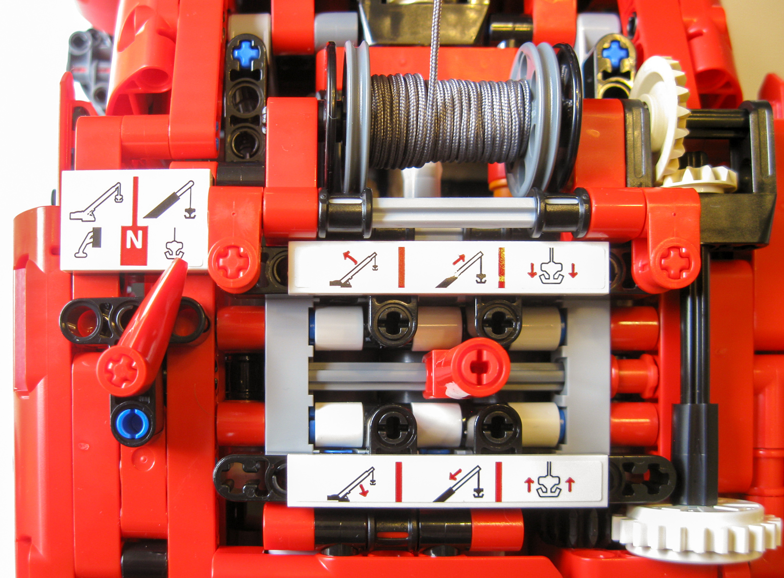
Function selectors and spooling system.
On to the motorized functions. The outriggers are highly geared down, and so very slow. They are not able to lift the whole vehicle, but they do take a noticeable amount of weight off the wheels and provide extra stability. All the other functions run at a very decent speed given the size and weight of the model, and there is no significant straining of the motor. The superstructure rotation in particular is a joy to behold. There is only one stud of theoretical vertical clearance between parts of the superstructure and parts of the chassis below, but the model is so sturdy and well designed that there is no chance of any rubbing or collisions!
As regards the crane itself, the boom lifts from almost horizontal to almost vertical, and the length when fully extended is amazing. Two sliding pulleys allow the string carrying the hook to spool neatly onto its drum. Once again, all these functions are smooth, strong, and surprisingly speedy. One annoyance is that the string needs to be let out to allow the boom to extend. In principle this could have been done automatically using a differential mechanism, as was done in an earlier mobile crane, set #8421. It might also have been nice to see a three-section boom, like in #42009, but we can’t have everything!
The functions tend to have most of their gearing down towards the end of the gear train, near the function itself. This is a good design choice, because it means that most of the drive train is under low torque.
In a sense there is nothing new in the functions—all of them have been seen before in previous sets, and there are no completely new mechanisms. However, they all work exceptionally well, an impressive feat in such a huge model.
As a maximum stress test (within the limits of what can be reasonably expected), I tried raising and rotating the boom from its horizontal and fully extended position, with one of the larger wall sections attached (probably not a good idea with a real crane)! Even here, performance was admirable, with very little sign of strain.
It’s interesting to compare with another Technic behemoth, the Bucket Wheel Excavator #42055 from a couple of years ago. That set was a mechanical marvel with many innovative features, but one always had the feeling that it only just worked – everything seemed just on the limit of what LEGO parts were capable of. There’s none of that feeling with the Rough Terrain Crane. The motion of the functions feels powerful, robust and confident.
About the parts
Perhaps surprisingly, this set contains no new parts. There seems to be only one new color for an existing part, but it is a welcome one: the quarter-circle gear rack (24121) in black (8 of them). There are several relatively new part colors that are to be found in other 2018 sets also.
Part #24121 Gear Rack 11 x 11 Curved, new in Black!
At 7.4 cents per piece, the set is great value. The number and variety of pieces mean that it could serve as a decent-sized Technic collection all on its own!
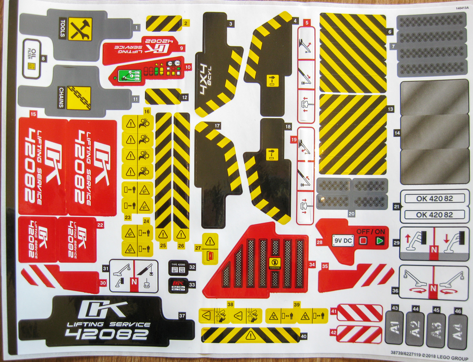
Sticker Sheet.
The instructions come in two thick books, and the sticker sheet includes a variety of warning signs, as well as labels for the control levers to indicate which functions they control. I’m not a fan of stickers, so I only applied the function labels. I think the model looks great without the other stickers.
Conclusion
I was prepared for disappointment, but in the end I really enjoyed this set. I give #42082 Rough Terrain Crane our highest Must Have (5/5) rating! Although there are no genuinely new mechanisms, and from a theoretical standpoint there are a few minor flaws, in practice the functions all work really well. The model is HUGE, and moreover it is remarkably solid, rigid, and strong. And it looks beautiful. The completed model has real play value. It’s great to have a crane that can actually lift something. Finally, it’s great value and a super parts pack.

#42082 Rough Terrain Crane (Photo: The LEGO Group.)
The LEGO Group provided this set for the purposes of this review. The opinions in this article are strictly my own—providing sets for review does not guarantee a positive review. Photos in this article are by Alexander Holroyd unless otherwise noted. Visit the About page for more info about our journalistic standards and affiliate programs.
I built this kit however the outrigger legs at front don’t work, the rear ones go up and down no problem but there is no shaft rotation out of the gearbox for the front set of outriggers. Any idea why this is ?
I’m afraid that I didn’t build it, so I’m not sure what could have caused this. I would revisit the gearbox section of the instruction booklet.
A small question I’m on part 208 and I have noticed that the gears don’t turn are they ment to or should I start again
Graeme,
I’m sorry but I didn’t build the model so I’m not sure. I suspect that it should be able to spin – it’s rare that gears won’t spin partway through the assembly.
In general the gears should turn, although you don’t say which exactly gears you are referring to. Bear in mind that the turntable is heavily geared down, so it may not be easy to back-drive it. It’s best to check that all mechanisms move freely at every step, to avoid having to go back a long way to fix the problem.
Hi guys,
My 8 year old boy has just finished building the crane all by himself. Super proud dad here!
However there is a problem with the outrigger legs. When he tries to lower them the two at the front go down but the 2 at the back go up! And vice versa.
Any idea what might be wrong? Any help is much appreciated.
Thanks in advance.
That’s impressive for an 8 year-old! The most likely cause is that the two of the four tan 12-tooth bevel gears in the linear actuators are placed incorrectly. You can see them at the extreme left and right of this picture: http://brickarchitect.com/wp-content/uploads/2018/08/IMG_3246.jpg
Note that (with the orientation of this picture) they are at the left side of the black 12-tooth double bevel gear at both ends of the chassis.
Great review, I’d like to know if I need to completely undo the 1st model to build the 2nd one?